
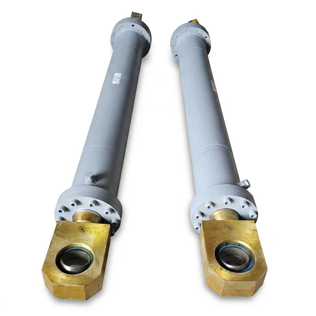
Why Cylinder Mounting Style Governs Mechanical Lifespan
In industrial machine design, a hydraulic cylinder is engineered strictly as a linear unidirectional force actuator. It is designed to push or pull along a pure axial centerline. It is not an axle, a structural beam, or a mechanical guide rail.
Selecting the incorrect mounting geometry or failing to account for frame deflection under high tonnage introduces the single most destructive force in fluid power: parasitic side-loading. Just 3% to 5% off-axis side load across an extended stroke length creates intense metal-on-metal friction, ovalizes internal bronze guide bushings, causes one-sided chrome rod score lines, and destroys dynamic seals within weeks.
Hydraulic cylinder mountings are divided into three broad mechanical families per ISO 6020/6022 and NFPA standards: Centerline Fixed Mounts, Pivot/Pivoting Articulated Mounts, and Foot/Side Lug Mounts.
Fixed Centerline Mounts: Front Flange vs Rear Flange Dynamics
Centerline mounts absorb thrust and tension directly along the central axis of the cylinder barrel. Because the mounting bolts are loaded in pure shear or tension rather than bending, centerline mounts represent the strongest and most rigid mounting configuration available:
- Front Flange Mount (Head Flange / MF3 / MF1): The mounting flange is integrated into the front rod gland head. This is the optimal configuration when the cylinder is used primarily in tension (pulling load). In tension, the pulling force transmits directly through the flange against the machine bulkhead without placing the cylinder barrel or tie rods in tensile stress.
- Rear Flange Mount (Cap Flange / MF4 / MF2): The mounting flange is located on the rear blind end cap. This is the ultimate configuration for high-tonnage thrust (pushing load) applications like hydraulic presses, balers, and injection moulding clamping platens. The immense reaction thrust pushes the rear base directly against the machine frame bolster plate, sparing the mounting bolts from continuous fatigue stress.
Pivot Mounts: Clevis (MP1/MP5) vs Trunnion (MT1/MT2/MT4)
When the driven machine element moves through an arc—such as a dump tipper bed, an excavator boom, or a toggle clamp linkage—the cylinder must pivot freely to remain aligned with the load vector:
| Mount Type | Pivot Axis Location | Key Engineering Advantages | Buckling Column Length ($L_e$) |
|---|---|---|---|
| Rear Clevis (MP1 / MP5) | Rear cap pin hole & rod end eye | Allows angular rotation in a single plane. With spherical rod eyes (MP5), accommodates up to ±4° of cross-plane machine frame misalignment. | Longest effective column length ($L_e = 2 \times \text{Stroke}$). High buckling sensitivity on long strokes. |
| Intermediate Trunnion (MT4) | Cylindrical trunnion pins positioned mid-barrel | Shortens the unsupported overhang of the barrel, dramatically increasing Euler buckling column resistance. Positions center of gravity closer to pivot. | Significantly reduced column length ($L_e \approx 1.2$ to $1.5 \times \text{Stroke}$ depending on trunnion position). |
| Head / Cap Trunnion (MT1 / MT2) | Pins located on front head or rear cap | Ideal for compact machine recesses where clevis ears cannot swing or clear surrounding framework. | Moderate column length. |
Euler Column Buckling & The Mounting K-Factor Multiplier
A hydraulic cylinder under compressive thrust acts like an architectural structural column. If stroke length is long relative to rod diameter ($d_r$), the rod will buckle elastically long before hydraulic yield pressure is reached.
In Euler’s critical buckling equation ($P_{\text{crit}} = \frac{\pi^2 \cdot E \cdot I}{L_e^2}$), the effective buckling length ($L_e$) is determined by multiplying the fully extended cylinder pin-to-pin distance ($L$) by the mounting K-factor:
- $K = 0.5$ (Fixed - Fixed): Front flange or foot mount with guided load. The safest and most rigid configuration; allows minimum rod diameter for high tonnage.
- $K = 1.0$ (Pinned - Pinned / Guided): Rear clevis or intermediate trunnion with rigidly guided machine load.
- $K = 2.0$ (Pinned - Pinned / Unguided): Rear clevis mount connected to a free-swinging load without external guide rails (e.g., boom crane). Effective column length doubles, reducing allowable compressive tonnage by 75%!
When engineering high-stroke actuators for industrial automation, Honeywell Hydraulics sizes rod diameters against the exact Euler safety factor ($SF \ge 3.0$ minimum) based on your specific mounting style.