
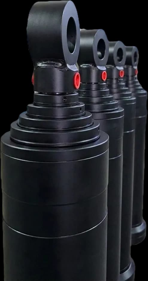
The Mechanics of Telescopic Actuators: Long Stroke in Compact Footprints
A standard single-stage hydraulic cylinder requires a retracted envelope length greater than its stroke length ($L_{\text{retracted}} \approx \text{Stroke} + \text{Dead Length}$). When machine geometries require immense stroke lengths—such as a 3,000 mm to 6,000 mm vertical travel in dump truck tipping bodies, agricultural hoists, and compact industrial scissor lifts—a standard cylinder is physically impossible to package.
A telescopic hydraulic cylinder (multi-stage cylinder) resolves this space constraint through a nested series of tubular steel sleeves (called stages or sleeves) of sequentially decreasing diameters that slide inside one another. A 4-stage telescopic cylinder can achieve a total stroke three to four times longer than its collapsed retracted envelope.
However, designing a reliable telescopic cylinder introduces unique fluid power dynamics: non-linear force output per stage, progressive speed acceleration under constant flow, and complex column buckling mechanics over full extension.
The Stage Force Paradox: Why Force Drops and Speed Jumps During Extension
In standard hydraulic actuators, force and speed remain constant throughout the stroke for a given pressure and pump flow rate. In a telescopic cylinder, every stage operates with a completely different effective cross-sectional area ($A = \frac{\pi \cdot d^2}{4}$).
Under constant pump flow ($Q$) and maximum relief pressure ($P$), the cylinder exhibits two dramatic behavioral shifts as each consecutive stage extends:
- Force Decreases Sequentially: The largest barrel (Stage 1) extends first because its large piston area generates maximum thrust at the lowest pressure required to break static friction ($F = P \cdot A$). As Stage 1 bottoms out, Stage 2 extends with a smaller area, generating significantly less push force. The final (smallest) stage provides the lowest force capacity.
- Extension Speed Increases Sequentially: Velocity is inversely proportional to cross-sectional area ($v = \frac{Q}{A}$). Because pump flow rate ($Q$) is constant, each successive smaller stage extends dramatically faster than the preceding stage.
This dynamic creates the classic "telescopic staging profile" that perfectly matches tipper dump truck mechanics: when the tipper bed is horizontal, maximum force is required to break the load off the chassis rails; as the bed tilts upward toward 50°, gravity shifts the load off the body, requiring much less thrust but faster completion.
Total Fluid Displacement & Reservoir Sizing for Telescopic Systems
One of the most frequent installation errors in mobile and industrial equipment is undersizing the hydraulic oil reservoir for a multi-stage cylinder. Because single-acting telescopic cylinders consume fluid during extension without returning fluid to the tank, the reservoir must hold enough reserve oil to prevent pump cavitation at maximum extension.
Total displaced volume ($V_{\text{total}}$) is calculated by summing the internal volume of all individual extending stages:
For example, a typical 3-stage tipper cylinder with stage diameters of 125 mm, 105 mm, and 85 mm each traveling 1,200 mm stroke displaces approximately 32.2 liters of hydraulic fluid. If the vehicle reservoir only holds 40 liters, the oil level drops dangerously close to the pump suction strainer at full dump angle, causing air vortexing, pump cavitation scream, and rapid pump failure.
Honeywell Hydraulics recommends that the working oil reservoir capacity should equal at least 1.5 times total extended cylinder displacement plus a safety reserve to maintain complete pump inlet submergence on sloped terrain.
Euler Column Stability & Side Load Prevention on Long Strokes
When a 4-stage cylinder extends to 4,000 mm or 5,000 mm length under a compressive axial load, it behaves as a slender column subject to catastrophic Euler column buckling. Because the wall thickness of nested sleeves is constrained by packaging, structural stability is paramount:
- Bronze Guide Ring Spacing: High-leverage side loads are absorbed by dual high-tensile phosphor bronze or phenolic guide wear rings installed at the base of each sleeve and inside the head glands. Increased overlap between stages (minimum 15% to 20% sleeve length overlap) dramatically increases buckling resistance.
- Hard Chrome Plating Integrity: Every nested sleeve must be precision ground to an outer surface finish of $Ra \le 0.2\,\mu m$ and micro-crack hard chrome plated to a minimum thickness of 25 to 35 microns with a surface hardness of 850 to 1,000 HV. This prevents sleeve galling when abrasive dust settles on extended stages.
- Self-Aligning Mountings: Telescopic cylinders should always be mounted with spherical rod clevises or trunnion pins that permit free angular articulation. Rigid rigid-clevis or foot mounting introduces severe bending moments that will score sleeve barrels within days of operation.